In 1935, the British Government took the courageous decision to
carry all mail within the Empire at the ordinary inland surface
rate of a penny ha'penny. To cope with this and increasing passenger
traffic required a substantial expansion of Imperial Airways who
took the equally courageous decision to buy 28 of a completely
new flying boat straight off the drawing board from Short Brothers.
At that time, flying boats were better suited for heavy loading
than land planes which were constrained by the small and rough
landing fields then available. The resulting aircraft was the
Short Empire C-class flying boat, the prototype of which made
its maiden flight on 4th. July 1936. The military potential of
the design was quickly appreciated and the Sunderland was quickly
developed. The two-deck layout of the Empire boat was retained,
with wardroom, crew's quarters, sleeping quarters, galley and
workshop. The prototype first flew in October 1937 and the Mk.I,
powered by Pegasus XXII engines, entered service the following
summer. At the start of WW2, three squadrons of Sunderlands were
in service. As well as valuable work on maritime patrol, they
also performed a considerable amount of transport work, evacuating
hundreds from Norway, Greece and Crete. At the end of 1941, the
Mk.II was put into production with the Pegasus XVIII powerplant
and later versions featured a two-gun dorsal turret. The Mk III,
the most numerous version, appeared in 1942, with the Mk.IV and
Mk.V following. The aircraft is perhaps best known for its role
in the defeat of the U-boat, claiming its first in January 1940.
Its formidable armaments earned it the nickname of "Flying
Porcupine" and many Ju 88s were included in its list of kills.
In the early years of the war, the shortage of Sunderlands was
augmented by the transfer of Empire boats from British Airways
to military duties. In 1943 as the situation eased, the procedure
was reversed with a batch of Sunderlands being demilitarised for
civilian use by the airline. With a wingspan of 112 ft. and a
crew of thirteen, the Sunderland Mk.V had a maximum speed of 213
mph and a normal range just short of 3,000 miles. Production finally
ceased in October 1945, with a total production of over 700 aircraft,
including 250 machines being completed by Blackburn Aircraft Ltd.
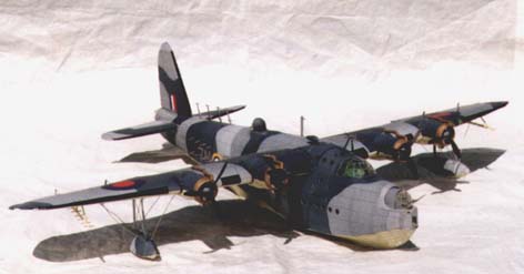
At a scale of 1:33, the model is large, with a wingspan of over
three feet. This is larger than any aircraft I had so far built
so I approached the project with some trepidation. Also, this
is not a conventional aircraft, but a flying boat with construction
more akin to a ship. The kit itself is printed on 11 sheets of
A3 card with a further 8 sheets of paper parts to be backed up
onto stiff card. Normally, with these latter, I cut out the parts
roughly and stick them onto scrap card such as cereal packets.
However, in this case, because of the sheer numbers of sheets,
I decided to glue whole sheets to A3 sheets of plain card. For
this purpose, I used Spraymount aerosol adhesive which was much
quicker and cleaner than spreading glue from a tube over a large
area. I started by studying the four double-sided pages of diagrams,
which, since all instructions are in Polish, are essential. It
is here that you begin to appreciate that this model will be quite
a project.
The first part to be built is the hull/fuselage. Unlike the fuselage
of a land-based aircraft model which is built from a series of
cylindrical sections, the Sunderland's skeleton hull resembles
that of a ship model with keel and frames. As such, the Sunderland
is a full hull model and there are two separate decks to be inserted
into the structure, with steps in the deck towards the aft of
the aircraft. As it is quite complicated, the two guiding principals
are constant reference to the diagrams and construct generally
in part number order. As well as the skeleton parts, there are
also the cockpit interior and forward turret housing to be built
at this time and located in the hull. Along the edges of the skeleton
hull are glued a series of card strips on which the hull plating
will hang. The diagrams also indicate the use of brackets (sklejki)
made from scrap card and located between the deck-end, keel and
frame to stabilise the butt joints. At this stage also, two pairs
of half-length wing spars are attached to the hull skeleton; as
the attachment of the wings is some way ahead, these can become
bent and weakened unless the hull is supported in an upright position.
Plating the hull comes next. Many of the plates, especially forward,
have portholes which may be glazed. At the same time, the cockpit
canopy must be positioned and the gun turrets, which can rotate,
built up and located inside the fuselage. These latter are especially
difficult, the gun turret frames being quite tricky to glue together.
I found that using small tabs with which to join two sections
of a frame was preferable to relying on butt joints. I glazed
the turrets from flat sheets of perspex, cut according to the
templates provided. I found it was better to stick the perspex
piece into shape before inserting into the turret frame. Having
completed the hull, the next stage was the wings. Again it was
back to the diagrams to get a clear picture of what should be
done. The wings are provided with mechanisms for moveable ailerons
and flaps. For the latter, I used sections of copper wire which
allowed the flaps to extend from the back of the wing and then
pivot downwards. For the ailerons, I used styrene rod to produce
a suitable hinge. Locating the wings on the stub spars proved
quite tricky. The spars are located in narrow sheathes in the
end of the wing and care must be taken to slip these on before
the glue begins to bind. In the end, I had to ease open the sheathes
with a screwdriver to allow the spars to be pushed right in.
The fin and tail-planes are built next and again both the rudder
and elevators can be made to move. The two pontoons are constructed
like miniature versions of the hull with frames and plating. These
are then attached underneath the wing and braced with wires; I
found these latter essential to give the pontoons stability. The
engines are built in three sections. Firstly, there is the fairing,
again made with frames, followed by the cowling with propellor.
Finally, the exhaust pipe which is very neatly made from various
tubular sections to bend in the right way; onto the pipe, and
this is what took the time, are glued about 50 small wedge-shaped
vents. Happily, the final effect is quite pleasing.
Finishing off the model includes attaching an array of radio aerials
and underwing bomb-racks with a full complement of bombs. A set
of wheels to be attached to the hull for movement on land is also
provided and these could be used as a suitable cradle for displaying
the model. Not all the plating fitted perfectly, because of either
me or the kit, but I was able to patch some sections with spare
coloured card provided with the kit. Touching up with acrylic
paint completed the process.
I would estimate the model took me upwards of 200 hours to build
and the finished result is well worth the effort. It is the first
time I have made a large, four engined aircraft and a seaplane
to boot. It is definitely not a beginner's model but anyone of
reasonable experience should find it an enjoyable challenge. Overall,
I am pleased with this magnificent model.
Christopher Cooke